
Product Overview
Category: Secondary Water Supply SystemsSYWG Fully Automatic Non-Negative Pressure Water Supply System. Integrated pressure boosting equipment for building and municipal water supply. Contact Shenyin Pump for duty-point review, materials and configuration options.
- Duty-point review and pump selection support
- Outline drawings and installation instructions available
Export inquiry support
Need help selecting SYWG Fully Automatic Non-Negative Pressure Water Supply System?
Send flow, head, medium, temperature, voltage/frequency, quantity and destination country. Our engineering team can review duty point, materials, seal type and configuration for OEM, EPC and export projects.
Technical Information
The information below is for reference. Final order data is subject to the technical agreement and product nameplate.
I. Product Overview
The SBLW fully automatic non-negative pressure steady-flow water supply system is an integrated water supply unit developed based on variable-frequency technology. It connects directly to the municipal water supply network without creating any negative pressure within that network. Capable of replacing traditional storage tanks, it utilizes the existing pressure of the municipal network for direct or booster supply, thereby preventing secondary pollution and the waste of pipeline pressure energy. This results in significant savings on infrastructure investment and shorter construction periods.
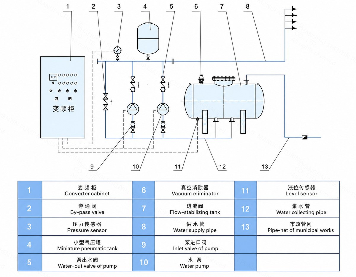
The SBLW system comprises a variable-frequency control cabinet, a steady-flow tank, a pump assembly, instruments, and a valve/piping assembly. It is suitable for water supply systems connected to a municipal network that require increased pressure and constant flow.
Environmental Conditions
1. Ambient temperature: 5–40°C
2. Relative humidity: ≤85% (at 20±5°C)
3. Medium temperature: 4–70°C
4. Power supply voltage: 380V (+5%, -10%)
II. Product Features
1. No need for water storage tanks—cost and energy savings
The SBLW system reduces investment costs and promotes energy conservation. Generally, using this intelligent non-negative pressure steady-flow system lowers expenses associated with tank construction (specific savings depend on the project plan). By utilizing municipal network pressure, it can reduce electricity consumption under certain operating conditions, with actual savings depending on site-specific parameters.
2. Easy installation and compact footprint
The SBLW system can be equipped with either a horizontal or a vertical steady-flow tank. Each type has distinct characteristics: the horizontal tank occupies less vertical space, while the vertical tank has a smaller floor footprint. The design, manufacturing, and inspection of the steady-flow tank comply with the GB150 standard ("Steel Pressure Vessels"); however, as the tank does not store compressed gas, it is not classified as a pressure vessel subject to specific pressure vessel regulations. 3. Versatile Application and High Level of Intelligence
The SBLW fully automatic, non-negative pressure, steady-flow water supply system utilizes advanced variable-frequency control technology. It features protections against overload, short-circuit, over-voltage, under-voltage, phase loss, overheating, and motor stall, as well as soft-start capabilities. The system can issue alarms, perform self-diagnostics, and diagnose faults under abnormal conditions, while automatically adjusting the water supply flow rate based on demand.
III. Working Principle
Upon commissioning, water from the municipal mains enters the steady-flow tank; air inside the tank is expelled through the vacuum eliminator, which closes automatically once the tank is full. When the pressure and flow rate of the municipal mains meet demand, the system supplies water directly to the distribution network via a bypass. When municipal pressure is insufficient, a remote pressure gauge sends a signal to the variable-frequency control cabinet; the pump starts and automatically adjusts its speed based on demand to maintain constant pressure. If the operating pump reaches full-speed (grid frequency) operation, a second pump starts and operates under variable-frequency control. During operation, if the municipal supply exceeds the pump's flow rate, the system functions in a "relay supply" mode. During peak demand, if the municipal supply falls below the pump's flow rate, water stored in the steady-flow tank serves as a supplementary source to ensure continuous supply; simultaneously, air enters the tank through the vacuum eliminator to break the vacuum, thereby preventing negative pressure in the municipal mains. Once peak demand passes, the system reverts to the relay supply state. If the municipal water supply is cut off, causing the water level in the steady-flow tank to drop, a level sensor sends a signal to the variable-frequency controller, and the pump automatically shuts down to protect the pumping unit. IV. Installation Instructions
1. During installation, the weight of the piping must not be borne by the pump itself; otherwise, the pump may be damaged.
2. Anchor bolts must be tightened securely during installation. Periodically check the pump to ensure these bolts remain tight; failure to do so could lead to severe vibration upon startup, adversely affecting pump performance.
3. Before installation, carefully inspect the flow passages for any hard foreign objects (such as stones or iron filings) that could impede operation or damage flow-path components during running.
4. To facilitate maintenance and ensure safe operation, install a valve on both the inlet and outlet pipelines and a pressure gauge near the pump outlet. Additionally, to prevent water hammer and backflow during shutdown or sudden power failure, install a check valve upstream of the outlet gate valve; this ensures optimal operating conditions and extends the pump's service life.
5. If the pump is used in an application requiring suction lift, a foot valve must be installed. The inlet piping should have minimal bends and must be completely free of air or water leaks to avoid compromising suction performance.
6. Install a strainer upstream of the pump inlet to prevent impurities from entering the pump, clogging flow passages, and impairing performance.
7. Before installing the piping, rotate the pump's rotor assembly by hand; it should turn freely without any sounds of friction or signs of binding. If binding or friction occurs, disassemble the pump to investigate the cause.
Startup and Operation
1. Rotate the motor by hand; the impeller should turn smoothly without any grinding or scraping noises.
2. Open the inlet valve and the air vent valve to fill the pump chamber with liquid, then close the air vent valve;
3. When transporting hot liquids, preheat the pump before startup at a rate of 50°C/h; preheating is achieved by continuously circulating the pumped liquid to ensure uniform heating of all components;
4. Rotate the shaft by hand a few times to allow lubricating water to reach the mechanical seal faces;
5. Jog the motor to verify the correct direction of rotation;
6. Fully open the inlet valve and close the discharge line valve;
7. Connect the power supply; once the pump reaches normal operating speed, gradually open the discharge line valve and adjust to the required operating conditions;
8. Monitor instrument readings and check that the temperature rise of the motor and bearings does not exceed 70°C; address any abnormalities promptly.
Shutdown
1. Gradually close the discharge line valve and cut off the power supply;
2. Close the inlet valve;
3. If the ambient temperature is below 0°C, drain the liquid from the pump to prevent freezing and cracking;
4. For long-term shutdowns, disassemble, clean, and properly package/store the pump.
Operational Maintenance and Care
1. The inlet piping must be tightly sealed to prevent water or air leakage;
2. Do not operate the pump under cavitation conditions for extended periods;
3. Do not operate the pump at high flow rates that cause the motor to run in an over-current state for extended periods;
4. Regularly check the motor current during operation and aim to keep the pump operating within its design range;
5. Assign personnel to monitor the pump during operation to prevent accidents;
6. Strictly prohibit the mechanical seal from running dry;
7. Rotate the pump (motor) shaft a few times before startup to prevent mechanical seal breakage caused by sudden starting;
Product Diagrams and Reference Images
Model Designation
SYWG20-60×2-600
Shenyin Non-negative Pressure Water Supply Equipment
Single Pump Flow Rate (m³/h)
Single Pump Head (m)
Number of Pumps
Flow Stabilization Tank Size